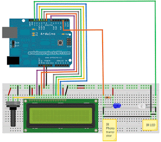
Para isso monte sua pcb conforme está na figura:
Atente-se que nem sempre o display lcd vem na ordem exata de montagem. Se voce comprar o display lcd original pra arduino, ele vira nessa configuração, mas um "piratão" que foi o que eu usei, veio em outra configuração.
Aqui esta a configuração de um display original
Se voce ler nas entrelinhas que as posições sao invertidas, só brincar de batalha naval e "cruzar" as posições, caso contrario monte conforme esta desciminado na primeira imagem.
Bom, a parte de hardware montada e testado os sensores se acompanhou meu posta anterior, vamos ao que interessa :):):)
Este código eu removi de um site americano
-----
/*
 * Optical Tachometer
 *
 * Uses an IR LED and IR phototransistor to implement an optical tachometer.
 * The IR LED is connected to pin 13 and ran continually.
 * Pin 2 (interrupt 0) is connected across the IR detector.
 *
 * Code based on: www.instructables.com/id/Arduino-Based-Optical-Tachometer/
 * Coded by: arduinoprojects101.com
 */

int ledPin = 13;                // IR LED connected to digital pin 13
volatile byte rpmcount;
unsigned int rpm;
unsigned long timeold;

// include the library code:
#include <LiquidCrystal.h>
// initialize the library with the numbers of the interface pins
LiquidCrystal lcd(7, 8, 9, 10, 11, 12);

void rpm_fun()
 {
   //Each rotation, this interrupt function is run twice, so take that into consideration for
   //calculating RPM
   //Update count
      rpmcount++;
 }

void setup()
 {
   lcd.begin(16, 2);  // intialise the LCD

   //Interrupt 0 is digital pin 2, so that is where the IR detector is connected
   //Triggers on FALLING (change from HIGH to LOW)
   attachInterrupt(0, rpm_fun, FALLING);

   //Turn on IR LED
   pinMode(ledPin, OUTPUT);
   digitalWrite(ledPin, HIGH);

   rpmcount = 0;
   rpm = 0;
   timeold = 0;
 }

 void loop()
 {
   //Update RPM every second
   delay(1000);
   //Don't process interrupts during calculations
   detachInterrupt(0);
   //Note that this would be 60*1000/(millis() - timeold)*rpmcount if the interrupt
   //happened once per revolution instead of twice. Other multiples could be used
   //for multi-bladed propellers or fans
   rpm = 30*1000/(millis() - timeold)*rpmcount;
   timeold = millis();
   rpmcount = 0;

   //Print out result to lcd
   lcd.clear();
   lcd.print("RPM=");
   lcd.print(rpm);

   //Restart the interrupt processing
   attachInterrupt(0, rpm_fun, FALLING);
  }
-------------
E pelo meu vídeo ele funciona super bem.
Para montagem os leds emissor e receptor, 1 resistor de 10k ohms, um potenciometro de 10 k linear, um display lcd, um arduino e bastante fios para os jumpers, além das protoboards e um motorzinho pra testar e claro.
Em breve postarei o vídeo, aguardem...
Como prometido, eis o vídeo:


Nenhum comentário:
Postar um comentário